How is the porosity of ePTFE created?
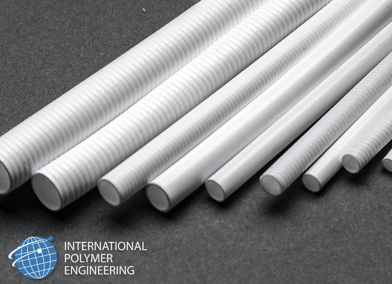
PTFE fine powder resins are used in the creation of expanded/ePTFE. These resins have a 95-98% crystalline structure and a high molecular weight which prevents the resin from flowing after reaching its melt phase. Therefore, PTFE resins are not melt extruded, but instead they are paste extruded (which is similar to ceramic processing).
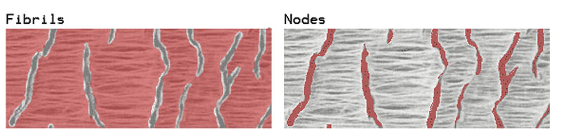
In order to create the porous structure in ePTFE the extruded profile will be mechanically expanded. The mechanical expansion is followed by amorphic locking, or “sintering”, of the expanded structure. The mechanical expansion of PTFE tubing creates a unique micro-structure of nodes and fibers, pictured in figure 2 below.
The porosity of ePTFE that is created by the expansion process can be measured in two different ways:
- Volume density
- Fiber length (also known as Internodal distance)
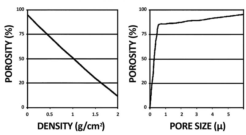
There is a direct correlation between the fiber length and the volume density – the greater the mechanical expansion, the longer the fiber length, and the lower the volume density. Non-porous PTFE has a volume density of 2.15 g/c cm, while IPE is able to expand to a volume density from less than 0.3g/cubic cm to over 1.0 g/cubic cm. The measurement of the fiber length (which is also called Internodal distance or IND) is not a measurement of the pore size; it is actually a measurement of the fiber length as measured with SEM or high end microscopy.
Those familiar with ePTFE implanted products will reference the internodal distance as related to various cellular responses to ePTFE material implantation. IPE has the processing capabilities of producing internodal distances of < 10 microns to >80 microns.
The physical strength properties of ePTFE in different porosities are considerably different. The expansion process of ePTFE and the resins used in those operations will increase the tensile strength. The main reason for the increase is that the crystallinity of ePTFE can be 95% or higher as compared to the 40-50% crystallinity of PTFE products. There are also various patented methods that can be applied to ePTFE processing that further increase the strength of the material.
How does porosity affect the functional performances of ePTFE?
ePTFE is designed into various applications in a wide variety of industries from hydrophobic censor covers and vascular grafts to instrument covers, and much more. Ensuring the correct material porosity and material thickness in order meet various functional requirements is incredibly important to take into consideration when designing with ePTFE.
In general, the higher the porosity (lower volume density or the higher the internodal distance) the ePTFE material will become:
- Softer
- More compressible
- Higher flexural capabilities
- Lower tensile strengths
- Higher air permeability
- Greater tissue in-growth or endothelization of implanted products
Conversely, the lower the porosity (higher volume density or shorter internodal distance) will be:
- Stiffer
- Resist compression
- Lower flexural capabilities
- Higher tensile strengths
- Lower air permeability
- Reduced tissue in-growth or endothelization of implanted products
There must be a balance between the porosity and the dimensional considerations. The functional properties of ePTFE must be understood in the design of ePTFE. One must also consider bonding, attachment, or other secondary operations during the design phase.
Here are a few brief examples of design considerations:
1.) Medical instrument covers for highly articulating robotic or flexible bending sections. Typically the ePTFE is used in a tubular form that covers or protects internal laser cut metal frame bending sections to reduce tissue damage, reduce insertion forces of instruments into the body with its high lubricity, and prevents kinking or bunching seen in other polymer covers. In these cases the ePTFE can be relatively thin walled and fabricated in higher product volume densities. The diameter of the ePTFE tubing should be very close to the outer diameter of the product that it is covering. This will allow the ePTFE to flex along with the articulations without greatly increasing the force for the device to flex. A key feature of ePTFE is that the flexibility of the tubing is facilitated by the fibers which run down the longitudinal axis of the tubing. During flexion the thin flexible fibers are allow to fold or compress with little resistant or damage to the polymer structure.

2.) In non-supported tubular constructions like aeration or de-aeration tubing. The tubing porosity should be selected to provide the appropriate flow rate thru the tubing wall or capable of vacuum pressures needed for the application. The higher the pressures either internal or external to the ePTFE tubing will require thicker walls and lower porosities in the tubing to prevent kinking or collapse of the tubing during application. The diameter of the tubing can dictate the porosity and thickness of the tubing needed for each application. ePTFE is used in these applications due to its ability to be hydrophobic under low pressures while still being highly flexible. Also due to its high chemical and temperature resistance needed in specific applications where corrosive gasses or elevated temperatures are needed.
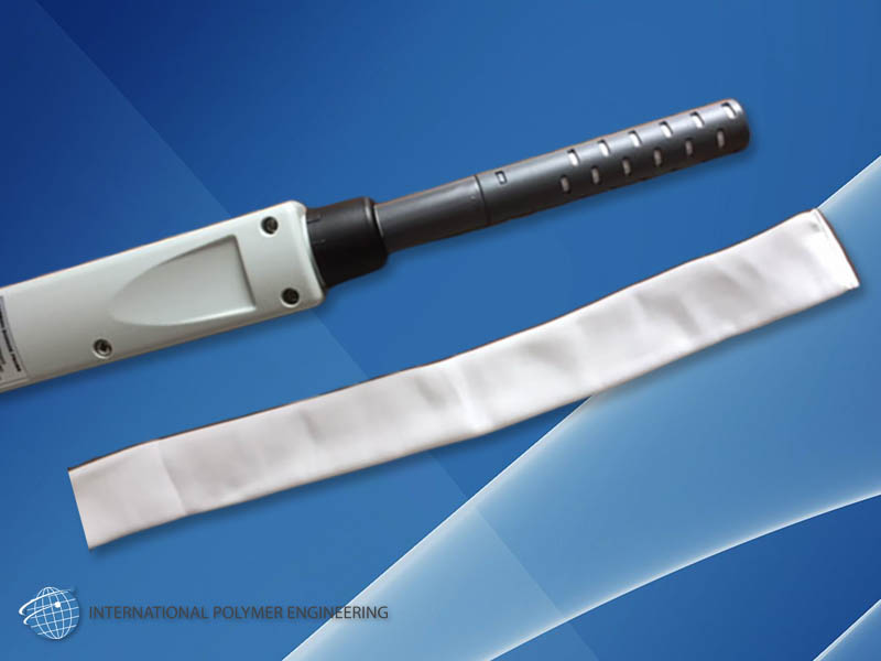
3.) In applications like gas monitoring systems like CO2 sensor for environmental soil, air, or water sampling. The ePTFE is typically a sleeve that fits over the sensor cap. The porosity in these types of applications is typically <.5g/c cm which will allow for quick reaction times while still being hydrophobic. Wall thicknesses can vary depending of the application to provide a product that will resist tearing which is susceptible of products with thin walled materials. The use of ePTFE for these applications is also beneficial due to the very low pore size (<1 micron) which will also act as a filter to prevent fouling of sensor equipment. IPE is also able to thermally seal the ends of the tubing to provide an easy to install sock like feature.
4.) Standard vascular bypass or graft tube applications the tubing is not typically internally or externally supported, there are exceptions. There needs to be a balance between the internodal distance, the tubing diameter, and the wall thickness. There are a lot of different configurations of vascular graft tubing available and each design may indicate difference in the internal or external porosity. The variance in the porosity between manufacturers is based on the endothelial or tissue in-growth requirements of those manufacturers. Some of these changes in porosity are related to the processing differences between manufacturers or the intentional manipulation to alter or change porosities through processing modifications. Changes in the porosity can either limit or promote tissue ingrowth on different surfaces of the ePTFE tubing. A majority of these tubes would have a volume density of .45-.75g/c cm or a 20-40 micron internodal distance. Since the tissue in-growth properties should be the main consideration in the design of this tubing. The diameter and wall thickness will be required to prevent kinking or collapse of this tubing during use based on the tubing internodal distance requested. A larger tube diameter would require a thicker wall final tube as compared to a smaller diameter which can have a thinner wall proportionately.
Combining different porosities of ePTFE for different applications and functional requirements.
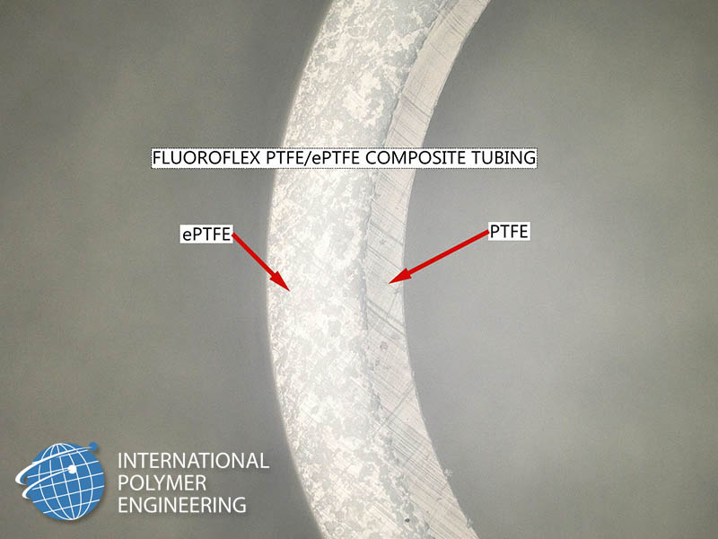
IPE has the capability for the creation of different material porosities through the cross section of the tubing or sheet material. This capability can provide a combined material property for functional or ingrowth properties. The thickness and the density/porosity of each layer will need consideration in the design of these specialized products. IPE’s biopsy channels combine a layer of non-porous PTFE on the internal surface and high density porous PTFE on the exterior surface. The combination of those layers allows for the best properties of both materials. The inner layer will prevent any longitudinal compression, provide a lubricous inner layer, allow for tubing to be cleaned with standard cleaning operations, and facilitate the ability to pressurize the tubing. The exterior layer will also provide a lubricious exterior surface but also creates a highly flexible product with a low wall profile.


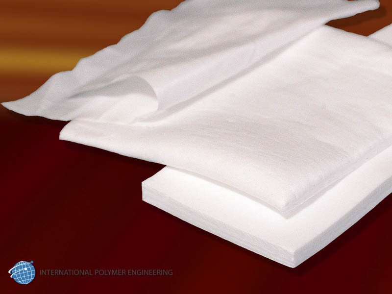
In sheet applications, IPE is able to alter the porosity of different through the thickness of the material. The variances in the porosity through the product can be proportionally changed based on functional and application requirements. For instance, combining the properties of non-porous PTFE thru the cross-section of ePTFE can provide structural reinforcements of ePTFE that facilitate the ability to carve or shape ePTFE into intricate devices.

International Polymer Engineering is one of the only plastic extruders who specialize in manufacturing custom ePTFE FluoroFlex™ and thermoplastic products. On top of our state-of-the-art rod, tube, and sheet extrusions we also offer bending, flaring, precision milling, and bonding; as well as design & development, material testing & analysis, and clean room processing. We are also ISO 13485:2016 certified to ensure stringent quality standards. IPE is your total solution provider.
When looking for a highly flexible, lubricious, chemically inert, hydrophobic plastic for critical applications, very few non-woven plastics can meet or exceed the flexural properties needed in barrier, instrument delivery, and bending sections of typical medical implants and industrial instruments like our FluoroFlex™.
For more information on our company and offerings please visit our website at www.ipeweb.com; or email us directly to get started today!
